Water turbines
Controls for hydro turbines
Hydraulic control units and drives for hydro turbines
Our portfolio


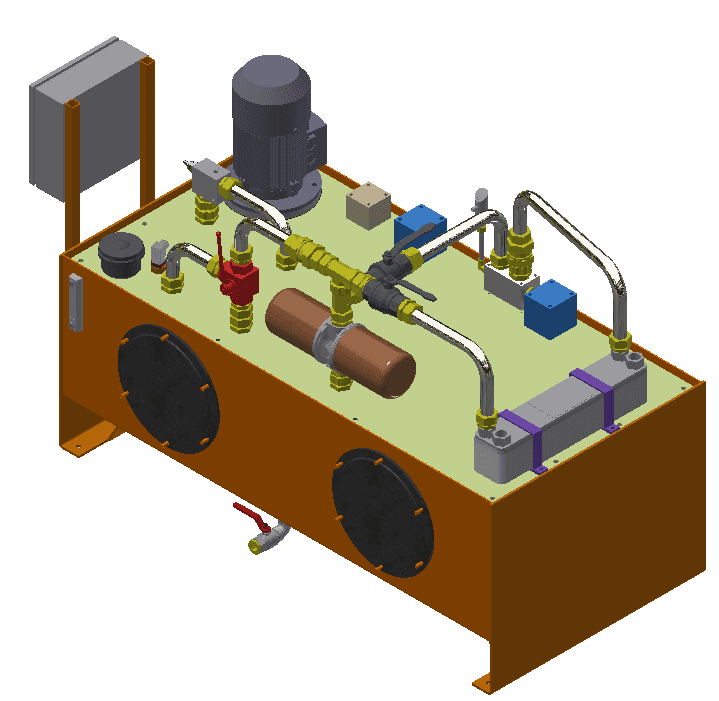
70l oil tank - 2.2 kw - motor, gear pump for Kapplan-turbine control
New design of a turbine control block for water turbines
Freely extendable by connecting plates with stackable systems for flaps, slides and other secondary functions.
Pressure filter block
Application possibilities:
- Gear pump with pressure relief and check valve
- Accumulator operation with gear pump, accumulator safety valve and accumulator drain valve
- Controlled pumps with pressure regulator and load sensing regulator with pressure remote control
- Controlled pumps with load sensing, regulation with extern load sensing signal
Turbine control block
for guide wheel, impeller type, beam steering and other control units. Compact in one control plate. Therefore, stackable systems with a lot of valves can be dispensed (will cause leakage). Any number from control elements can be installed. Only the black/white-, proportional- or the servo valve is flanged. Is a function not needed, the valve can be replaced by a plug.


Hydraulic unit for telescopic rake cleaner with skimmer
Technical specifications
Electric motor:
3 KW 1450 rpm 230 / 400V
Gear pump:
5,8l / min at 180 bar
Oil tank:
70 liter aluminum tank
The hydraulic power unit consists of:
- Oil tank 70 liters (aluminum)
- Oil sump elevated
- Gel absorber
- Level display optically
- Level temperature switch
- Tank heater with integrated thermostat
- Return filter with el. clogging indicator
- Hand pump
- E-Motor
- Gear pump
- Clutch and bellhousing
- Valve block with 3 functions:
- Lifting cylinder
- Pressure cylinder
- Escape protection
- All outgoing lines can be shut off
- Oil cooler connection prepared, cooler bypass installed
- El. components wired to terminal box
- Heating and electric motors can be switched off via the lockable service switch


Drive unit for an intake gate
Performance:
Electric motor:
3 KW 1450 rpm 230 / 400V
Gear pump:
5,8l / min at 200 bar
Oil tank:
250 liter tank
The hydraulic aggregate consists of:
- Container assembly with:
- Oil reservoir 250 liters
- Oil sump elevated
- Gel absorber
- Level display optically
- Level temperature switch
- Tank heater with integrated thermostat
- Return filter with el. clogging indicator
- Hand pump
2 pump assemblies with:
- E-Motor
- Gear pump
- Clutch and bellhousing
- Stopcock (connection of both pumps)

Valve block ground relief contractor with:
- Connection row plate 1 Compartment
- Intermediate plate with overpressure valve
- Throttling check valve in A - B (drain throttling)
- Unlockable check valve in A -B
- Pressure reducing valve in A with bypass check valve
- 4/3 directional control valve middle position P-A-B to tank 24 V DC
Valve block inlet contactor includes:
- Connection row plate 1 compartment
- Intermediate plate with overpressure valve
- Throttling check valve in AB (drain throttling)
- Unlockable check valve in A-B
- Pressure reducing valve in A with bypass check valve
- Emergency valve without current P-A and B-T 24 V DC
- 4/3 directional control valve middle position P-A-B to tank 24 V DC
Storage system consisting of:
- 2 pcs bladder storage 50 liters
- Storage security block
- Pressure switch programmable with two switching points
- El. Components wired to terminal box
- Heating and electric motors can be switched off via the lockable service switch
Turbinenmanagement Francis Turbine
Performance:
Electric motor:
2.2 KW 1450 rpm 230 / 400V
Gear pump:
5.8 l / min at 200 bar
Oil tank:
70 liter aluminum tank
Hydraulic power units include:
- Filling and ventilation filter
- Level display optically
- Level temperature switch
- E-Motor
- Gear pump
- Clutch and bellhousing
Keicher turbine block 1 segment for a Francis turbine Contains:
- Pressure filter in P with el. Clogging indicator
- Pressure relief valve in P
- Storage safety valve
- Drain plug storage
- Check valve in P
- 1 piece throttle check valve in B (speed emergency stop)
- 2 pcs 2/2 directional seat valves normally open 24 V DC (emergency shutdown)
- 1 pcs 2/2 directional seat valves normally closed 24 V DC (storage shut-off if no control movements take place)
- 1 pc load holding valve in A and B
- 1 pc 4/3 proportional directional valve with integrated electronics control +- 10V
- Programmable pressure switch with 1 pc switching point and 1 pc switching point and 1 pc of analogue output
- Mechanical pressure switch for emergency closure
- Bladder accumulator 10 liters
- 3-fold manifold mounted on turbine block, without valve assembly
- Stopcocks in outlets A-B
- Pressure gauge with stopcock


Control bottom outlet

Transmission lubrication unit and brake control

Weir